In the world of mechanical design and manufacturing, accuracy is everything. That’s where GD&T (Geometric Dimensioning and Tolerancing) plays a vital role. Whether you’re a student, engineer, or technician, mastering GD&T symbols gives you the ability to read and create precise technical drawings that meet industry standards.
In this blog, we’ll break down the most commonly used GD&T symbols, their functions, and real-world use cases—so you can become job-ready and design-ready in no time.
What Is GD&T and Why It’s Important in 2025?
GD&T (Geometric Dimensioning and Tolerancing) is a symbolic language used on mechanical engineering drawings to define allowable variation in part geometry. It ensures that parts will fit and function properly without the need for tight and costly tolerances.
In 2025, industries from automotive to aerospace are demanding engineers who can confidently apply GD&T in CAD drafting and quality control. Enrolling in GD&T training enhances your ability to read and use these symbols effectively, boosting your career potential and improving project accuracy.
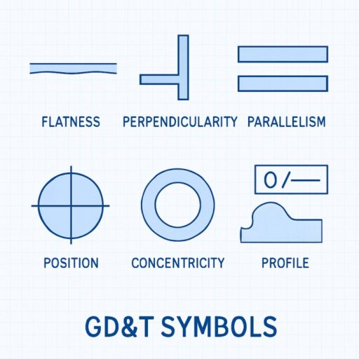
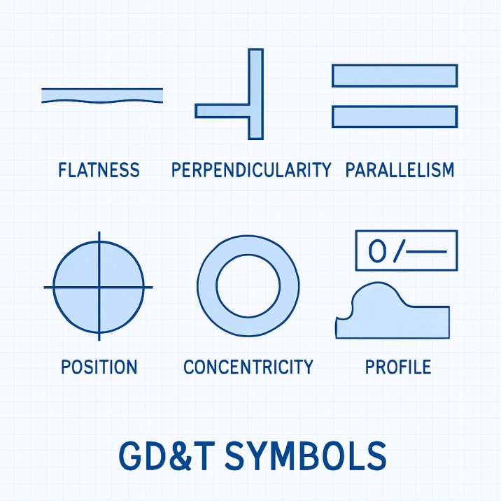
Key GD&T Symbols with Real-World Examples:
1) Straightness |⎯|
Straightness ensures that an element of a part is perfectly linear, without bends or curves. It’s crucial in shafts, rods, and sliders.
Real-world example: When manufacturing a CNC shaft, straightness ensures it doesn’t vibrate or misalign during rotation. Even slight deviations can lead to poor performance or total failure.
2) Flatness |⌶|
Flatness controls the evenness of a surface without referencing another. It ensures that parts sit or mount correctly.
Real-world example: Machining a steel base plate for a machine tool? Flatness ensures the base won’t rock or tilt, which could otherwise affect the entire setup.
3) Circularity / Roundness |◯|
Circularity (or roundness) controls how round a feature is across any cross-section. It ensures parts rotate smoothly and without wobble.
Real-world example: In pistons or bearings, circularity ensures that the rotating components don’t wear unevenly or vibrate.
4) Perpendicularity |⊥|
Perpendicularity guarantees that two surfaces are exactly 90° apart. It’s often used in brackets, supports, and structural parts.
Real-world example: In assembling a vertical support to a baseplate, this ensures it doesn’t tilt—maintaining strength and alignment.
5) Parallelism |∥|
Parallelism controls how two surfaces or features are aligned without touching. This is important in components that must slide or fit together.
Real-world example: In a hydraulic cylinder, parallel piston walls reduce wear and increase sealing efficiency.
6) Position |⭘|
Position is the most versatile and widely used symbol in GD&T drawings. It controls the exact location of features like holes and slots.
Real-world example: Bolt holes on an engine block must be positioned perfectly to avoid assembly issues. Even 0.1mm off could make parts unfit.
7) Total Runout |⌰|
Total Runout controls the surface variation of a part during rotation. It’s vital in shafts, gears, and rotating assemblies.
Real-world example: In gear shafts, total runout ensures smooth rotation without wobble, which is critical in high-speed machines.
How to Read GD&T Symbols in a Feature Control Frame?
GD&T symbols are presented in a Feature Control Frame, which consists of:
- The symbol (e.g. ⊥)
- The tolerance zone (e.g. 0.05 mm)
- Datum references (like A, B, C)
This frame helps manufacturers maintain tight control over shape, size, orientation, and location, even across complex parts.
Why You Should Learn GD&T in 2025?
With industries moving toward precision manufacturing and Industry 4.0, GD&T has become a must-have skill. Recruiters are actively looking for engineers who understand:
- Tolerancing in CAD
- Reading and interpreting complex drawings
- Quality inspection based on GD&T
Mastering GD&T in 2025 will not only boost your employability but also make you a smarter designer or QC engineer.
Conclusion:
Understanding and applying the Top GD&T Symbols is no longer optional — it’s a must-have skill for every mechanical design professional in 2025. Whether you’re involved in manufacturing, quality control, or CAD drafting, mastering these symbols ensures accuracy, reduces rework, and improves communication across teams.
If you’re serious about advancing your engineering career, enrolling in a structured GD&T course is the best way forward. From CADD Centre GD&T training programs to hands-on projects, gaining expertise in geometric dimensioning and tolerancing helps you stand out in today’s competitive job market.
Start your GD&T journey today and master the top symbols with real-world examples — your key to faster, smarter, and more precise design.
FAQs
Which industries use GD&T in 2025?
In 2025, automotive, aerospace, robotics, and precision manufacturing rely heavily on GD&T. Engineers skilled in GD&T symbols and tolerancing methods are in high demand for designing, inspecting, and assembling components.
How does GD&T training help career growth?
Enrolling in a GD&T training course helps engineers master technical drawings, CAD tolerancing, and inspection techniques. Certifications from trusted institutes like CADD Centre make professionals stand out in the job market.
What’s the difference between GD&T and traditional tolerancing?
Traditional tolerancing defines only size variations, while GD&T controls geometry, form, orientation, and location, ensuring complete functional accuracy. This makes GD&T more powerful for complex parts and assemblies.
What are the main GD&T symbols used in mechanical design?
The most common GD&T symbols include Straightness, Flatness, Circularity, Perpendicularity, Parallelism, Position, and Total Runout. These are used to control part geometry in CNC machining and CAD drafting.
Where can I learn GD&T symbols and their applications?
You can join specialized GD&T certification courses at institutes like CADD Centre, which provide hands-on training in GD&T, CAD drafting, and mechanical design practices, along with real-world projects.


